The Components
This is a 7 segment display:
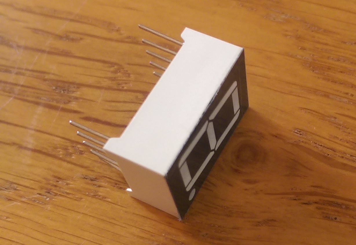 |
| A standard 7 segment display |
 |
| This one has pins on the top/bottom |
This one has pins at the top and bottom, but you can also get them with pins down the side. There are 7 pins to turn on each of the segments of the number, 2 ground pins and one for the decimal point to give a total of 10 pins.
 |
| Pin layout of the 7 segment display |
You may think this is impossible to hook up to the photon as it needs 8 digital output pins but you can add an intermediate component to abstract control of the individual segments away from the photon so you only care about the digital number. This component is the 4026 decade counter.
 |
| A 4026 decade counter IC |
 |
| I put stickers on my ICs to tell them apart |
This component takes in a clock signal, and for every cycle increments the output number and encodes it to 7 output pins that map to the a - g inputs of the 7 segment display. It can only count from 0 to 9 (hence the name decade counter) and it wraps back to 0 once 9 has been reached.
Here is a section of the 4026 datasheet:

You can see the output pins to drive the display and a couple of other pins I will explain in a minute.
The 4026 basically works like this:
1. Reset the component by toggling pin 15 HIGH then LOW. This will send power to all
output pins except 7 (the cross bar) to form a zero on the display
a 'one' on the display (12 and 13)
which can be hooked up to the clock pin of another 4026 decade counter to drive the
10's digit in a 2 digit number.
Where to get the components?
The best place I have found (from the UK) to get quite random components like this is bitsbox. Their stuff is pretty cheap and they seem to sell everything. I like to place an order for loads of random stuff (with plenty of duplicates in case I burn them out) and see what stuff I can make.
But if you've got to have a component now, now now, then maplin is probably the best place as you can just walk into a store and buy it, albeit at a premium price for the convenience.
I bought these components from bitsbox, the 7 segment display and 4026 decade counter.
How to hook it up
You need quite a few jumper leads to hook this up.

Photon to decade counter
- D6 to pin 15 (Vdd) - this provides power
- D0 to pin 1 (clock) - this provides the clock signal
- D5 to pin 3 (display enable in) - when this pin is HIGH it turns on the output pins. Without it you will get no signal sent to the display
Decade counter
- Pin 2 (clock inhibit) to GND - when this pin is HIGH it inhibits the clock from advancing the number. We don't want this to happen so ensure it is always LOW
- Pin 8 (Vss) to GND - standard ground output of the IC
- Pin 15 (reset) to GND - when this is toggled it will reset the counter to zero. We don't want this to happen so just connect it to LOW to stop any interference
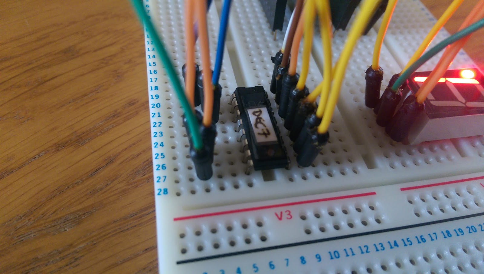 |
| Lots of connections required for the decade counter |
Decade counter to 7 segment display
- Just match up the output pins to the input pins of the display. I.e. connect output 'a' to input 'a' etc.
Photon to 7 segment display
- D7 to pin DP - only if you want the decimal point lit up
7 segment display
- Connect the 2 cc pins to GND
Phew! Ok now we've got all that hooked up we just need the little photon program to toggle the clock signal to increment the number on the display and set pins D5, D6 and D7 HIGH.
The code
The program is pretty simple. We want to provide power to the counter, also activate the output pins on the counter, and finally start toggling the clock pin.
 int clockPin = D0;
 int enableDisplay = D5;
 int counterPower = D6;
 int displayDecimalPoint = D7;

 void setup() {

   pinMode(clockPin, OUTPUT);

   pinMode(enableDisplay, OUTPUT);
   pinMode(counterPower, OUTPUT);
   pinMode(displayDecimalPoint, OUTPUT);

   digitalWrite(enableDisplay, HIGH);
   digitalWrite(counterPower, HIGH);
   digitalWrite(displayDecimalPoint, HIGH);
 }

 void loop() {

   digitalWrite(clockPin, HIGH);
   delay(500);
   digitalWrite(clockPin, LOW);
   delay(500);
 }
Once you flash this program onto your photon you should see the 7 segment display counting repeatedly from zero to nine.
No comments:
Post a Comment