Multimeters
This is my multimeter. It's pretty standard with no flashy extra abilities. It can measure voltage, current and resistance (and a couple of other things that I won't go into). One interesting thing to note is the fact that it can measure both AC and DC voltage (DC on the left hand side, AC on the right). With hobby electronics it is likely you will only ever be measuring very small DC voltages and won't need to measure AC. The AC measurement ranges are also scarily high (200/600) so unless you are an expert and know what you are doing I don't recommend you attach your probes to anything mains powered as it is very dangerous.
 |
| A multimeter |
You can get various types of probes to stick into the connector ports, but I just have standard pokey stick type ones. The probes are exactly the same other than their colour. Plug the black one into the COM port and the red one into the right hand VΩmA port and you're ready to start measuring things. (The left hand port is for measuring AC voltages and high currents up to 10A).
Voltage
Voltage is measured across 2 points in a circuit and is the difference in electrical potential energy between those 2 points, where one point has a higher positive charge than the other. (Check out this article for a more really good description of voltage).You measure voltage in parallel using the multimeter.
 |
| the multimeter is connected in parallel |
If you have a 3.3V source (like the photon) and you place your multimeter probes on the source and GND then you should get a reading of 3.3V.
You can measure points within a circuit to perform nodal analysis and see the voltage drop across individual components. For example if we hook the photon up to two 330Ω resistors in series we can measure across each resistor to see the voltage drop equally across them both.
 |
| The voltage measured in parallel across both resistors is 3.37V |
 |
| The voltage measured across just one resistor is 1.65V, half of the total voltage of the circuit |
Note: the multimeter is sampling the readings and taking an average so it is expected that they may differ a bit.
If we measure the current as well (4.93mA, see the next section) then we can validate these readings using Ohm's law:
V = IR
Voltage(V) = Current(A) x Resistance(Ω)
V = 0.00493A x (330Ω + 330Ω)
V = 3.2538V
Current
Current is a measurement of the number of electrons passing through the circuit per second. 1 amp is defined as 6.241*1018 electrons (1 Coloumb)/sec. Because you are measuring the flow of current you must connect your multimeter in series so the electrons flow through it.
 |
| the multimeter is connected in series |
We measured the internal voltage across the photon with no components connected and got a reading of about 3.3V. We mustn't do this with current though as this would involve creating a circuit of so little resistance it may damage the photon.
 |
| don't measure current in a circuit with no resistance |
Instead let's jump to measuring the current of a circuit with resistors. When we connect the multimeter in series with a circuit containing different numbers of resistors we can see the current changes. With one 330Ω resistor you get a current of 9.33mA and with two resistors you get 4.93mA.
 |
| The current measured in a circuit with one 330Ω resistor is 9.33mA |
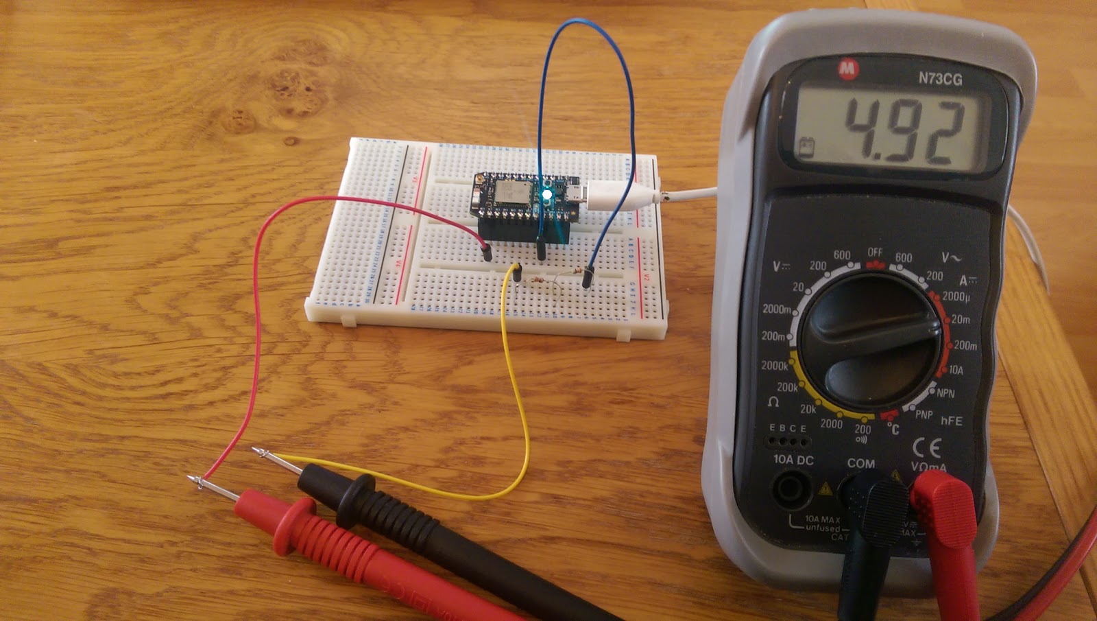 |
| The current measured in a circuit with two 330Ω resistors is 4.92mA |
What these measurements show us is that as the resistance in a circuit increases, the current decreases. This intuitively makes sense as if you put obstacles in the way of something flowing along, the movement will be slowed.
Again we can validate these readings using Ohm's law:
With two resistors:
V = IR
I = V / R
I = 3.3V / (330Ω + 330Ω)
I = 0.005A
I = 5mA
V = IR
I = V / R
I = 3.3V / 330Ω
I = 0.01A
I = 10mA
Note: Again, the multimeter does not give us completely exact readings so it is expected that they are a little bit off from the calculated current value
Resistance
Resistance is a measurement of how much an object opposes the flow of electrons through it. To measure resistance with your multimeter, connect the probes across the object. The multimeter will then pass a small current through it to measure the resistance. Do not try to measure resistance in a powered circuit as the current will mess with the multimeter's readings.
Here we can verify that the 330Ω resistor does in fact provide that much resistance:
 |
| The resistance is measured as 337Ω |
This is really nice to read the content of this blog. A is a very extensive and vast knowledgeable platform that has been given by this blog.
ReplyDeleteMultimeters