After a bit of googling I came across this article describing how to make various logic gates from transistors. So with a few components I had around I made AND, OR, NAND, NOR and NOT gates from scratch. I used the photon's tinker mode to turn on and off the inputs to test the gates. It was pretty simple once you get your head around what a transistor actually does but by the end I had a bit more respect for the modern chips that have billions of transistors in a single CPU.
What you will need
- 2 NPN transistors (I used 2N3904)
- 2 10kΩ resistors
- 1 4.7kΩ resistor
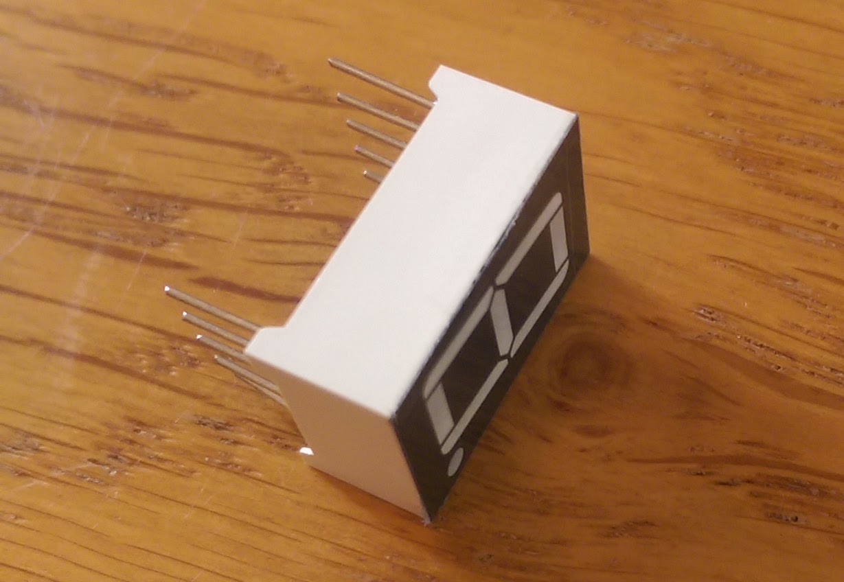
- 1 LED
A note on transistors
Transistors come in 2 flavours, NPN and PNP.
 |
| 2N3904 NPN transistor |
- NPN transistors do not let current flow through it unless the base input is charged. This means they are default off
- PNP transistors let the current flow through it unless the base input is charged, when the flow is stopped. This means they are default on
I'm going to choose to use NPN transistors here as I want the behaviour of current only flowing when the inputs are HIGH. You could equally make logic gates using PNP transistors but you just have a different circuit configuration to achieve the same effect. If you want more information about why NPN/PNP transistors behave the way they do, check out this article which explains it in detail.
Making the logic gates
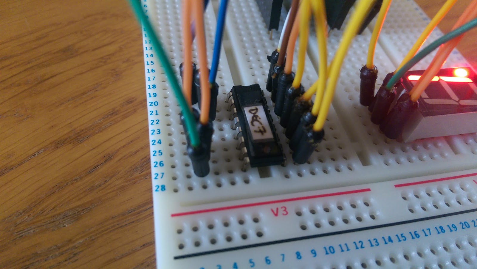
Each of the gates, except NOT, require 2 transistors; one for each input into the gate. We will connect the photon digital output pins D0 and D1 to a base input (the middle pin) of each transistor and this value will determine whether current flows across the transistor collector and emitter pins. We will then wire up the emitters and collectors in different configurations to create the different logic gates. A current will be provided across the transistors from pin D7 so keep that HIGH all the time.
Using the diagrams here as reference:
AND Gate
The finished AND gate:
 |
| AND Logic Gate |
D0 and D1 are the 2 inputs into the AND gate. They are each fed into a 10kΩ resistor and then into the middle pin of the transistor. D7 is providing the current across the transistors which are arranged in series by connecting the emitter of one transistor to the collector of the other. The emitter of the second resistor is then fed into an LED then out to ground.
How it works
If a current is applied to the base (middle pin), the transistor lets current flow across it. When you have 2 connected in series you need both D0 and D1 to be HIGH in order to let the current flow all the way across both transistors to the LED. If either of the pins are LOW then the current cannot flow to the LED. This gives us the behaviour of an AND gate.
OR Gate
The finished OR gate:
 |
| OR Logic Gate |
D0, D1 and D7 are used in the same way as the AND gate with the same 10kΩ resistors. The different here is that we connect the transistors to D7 in parallel rather than series. So we have a wire from D7 to each collector and then a wire from each emitter to the LED input. The transistors are entirely independent from each other.
How it works
Each transistor is independently connected to the LED. This means you only need to apply current to one of the D0 or D1 pins to cause current to flow to the LED. The LED will be lit in all input combinations except if both D0 and D1 are LOW. This gives us the behaviour of an OR gate.
NAND Gate
The finished NAND gate:
 |
| NAND Logic Gate |
D0, D1 and D7 are used in the same way as the AND gate with the same 10kΩ resistors. The transistors are also still connected in series. The differences here are that the LED is connected before the transistors instead of afterwards, and there is now a 4.7kΩ resistor between D7 and the LED/first transistor collector. The emitter of the second transistor is now connected straight to ground instead of the LED.
How it works
If a current is applied to the base (middle pin), the transistor lets current flow across it. When you have 2 connected in series you need both D0 and D1 to be HIGH in order to let the current flow all the way across both transistors to ground. When the transistors allow the current to flow, this provides a short circuit to ground and so no current flows to the LED. The LED will be lit in all input combinations except if both D0 and D1 are HIGH. This gives us the behaviour of a NAND gate.
NOR Gate
The finished NOR gate:
 |
| NOR Logic Gate |
This setup is a hybrid between the OR and NAND circuits. The transistor collectors are both connected to the 4.7kΩ resistor in parallel with their emitters both connected to ground. The LED is wired in above the transistors similar to the NAND gate.
How it works
As the transistors are independent of each other because they are connected in parallel (like the OR gate), you only need one of D0 or D1 to be HIGH to provide a short circuit to ground. This means the LED will only be lit when both D0 and D1 are LOW as this is the only configuration that allows current to flow through the LED. This gives us the behaviour of a NOR gate.
NOT Gate
This gate is a little simple than the rest as it only involves one transistor (because it only has one input). But it builds on what we learned from the NAND/NOR gates:
 |
| NOT Logic Gate |
D0 is the input source, we are still using the 4.7kΩ resistor after the D7 power source and the LED is connected before the transistor similar to the NAND/NOR gates. The transistor emitter is connected to ground.
How it works
If current is applied to the base (middle pin), the transistor lets current flow across it. As we have seen before, this allows the current coming from D7 to short circuit to ground instead of flowing round to the LED. This means the LED is lit when D0 is LOW as this is when current can flow to the LED and pulling D0 HIGH will turn off the LED. This gives us the behaviour of a NOT gate.
Conclusion
This exercise had no purpose other than satisfying curiosity as to how you would make logic gates from transistors. It is one thing looking at the Boolean logic tables and accepting that if the inputs are X and Y then the output is Z, and another to see it yourself in practice and understand why it is behaving like that.
I googled for how to make transistors but I'm not quite sure I want to go there...