I have known for a while that you can send data from the Photon to your computer via the serial connection and view it using the particle serial monitor. But I only recently found out that you can send data from your computer to the Photon too. For some reason I associated 'serial' with 'one-way' but it's really just 'one bit at a time'.
For example here is a small program that will echo back the data you send from your computer to the Photon if you have the serial monitor open:
 void setup() {

   Serial.begin(9600);
 }

 void loop() {

   int availableBytes = Serial.available();

   if (availableBytes > 0) {

     char message[availableBytes];

     for(int i = 0 ; i < availableBytes ; i++) {

       message[i] = Serial.read();
     }

     Serial.println(message);
   }

   delay(1000);
 }
You cannot send data to the Photon using the serial monitor as it can only receive data but you can send data using the CLI instead. On Linux you can run:
$> echo -e "hello world" > /dev/ttyACM0
This will send the characters 'hello world' over the serial connection to the Photon who will then read in the characters and print them back to the serial monitor.
After reading a bit about serial connections I found out:
1. Data is sent one bit at a time so it is pretty slow but adequate for talking to the Photon
2. Serial communication comes in 3 flavours:
Simplex - data is only sent in one direction
Half-duplex - data can be sent in 2 directions, but only one direction at a time
Full-duplex - data can be sent in 2 directions simultaneously
3. USB is a form of serial communication. USB 3.0 is full-duplex but earlier versions are only half-duplex. Full duplex data transfer helps USB 3.0 achieve it's super fast transfer speeds as it has dedicated wires for each communication direction.
After accidentally blowing up lots of components and failing to understand why my multimeter wasn't giving me readings I expected, I decided to invest a bit of time trying to understand exactly what I was measuring and how to do it properly.
Multimeters
This is my multimeter. It's pretty standard with no flashy extra abilities. It can measure voltage, current and resistance (and a couple of other things that I won't go into). One interesting thing to note is the fact that it can measure both AC and DC voltage (DC on the left hand side, AC on the right). With hobby electronics it is likely you will only ever be measuring very small DC voltages and won't need to measure AC. The AC measurement ranges are also scarily high (200/600) so unless you are an expert and know what you are doing I don't recommend you attach your probes to anything mains powered as it is very dangerous.
A multimeter
You can get various types of probes to stick into the connector ports, but I just have standard pokey stick type ones. The probes are exactly the same other than their colour. Plug the black one into the COM port and the red one into the right hand VΩmA port and you're ready to start measuring things. (The left hand port is for measuring AC voltages and high currents up to 10A).
Voltage
Voltage is measured across 2 points in a circuit and is the difference in electrical potential energy between those 2 points, where one point has a higher positive charge than the other. (Check out this article for a more really good description of voltage).You measure voltage in parallel using the multimeter.
the multimeter is connected in parallel
If you have a 3.3V source (like the photon) and you place your multimeter probes on the source and GND then you should get a reading of 3.3V.
You can measure points within a circuit to perform nodal analysis and see the voltage drop across individual components. For example if we hook the photon up to two 330Ω resistors in series we can measure across each resistor to see the voltage drop equally across them both.
The voltage measured in parallel across both resistors is 3.37V
The voltage measured across just one resistor is 1.65V, half of the total voltage of the circuit
Note: the multimeter is sampling the readings and taking an average so it is expected that they may differ a bit.
If we measure the current as well (4.93mA, see the next section) then we can validate these readings using Ohm's law:
V = IR
Voltage(V) = Current(A) x Resistance(Ω)
V = 0.00493A x (330Ω + 330Ω)
V = 3.2538V
Current
Current is a measurement of the number of electrons passing through the circuit per second. 1 amp is defined as 6.241*1018 electrons (1 Coloumb)/sec. Because you are measuring the flow of current you must connect your multimeter in series so the electrons flow through it.
the multimeter is connected in series
We measured the internal voltage across the photon with no components connected and got a reading of about 3.3V. We mustn't do this with current though as this would involve creating a circuit of so little resistance it may damage the photon.
don't measure current in a circuit with no resistance
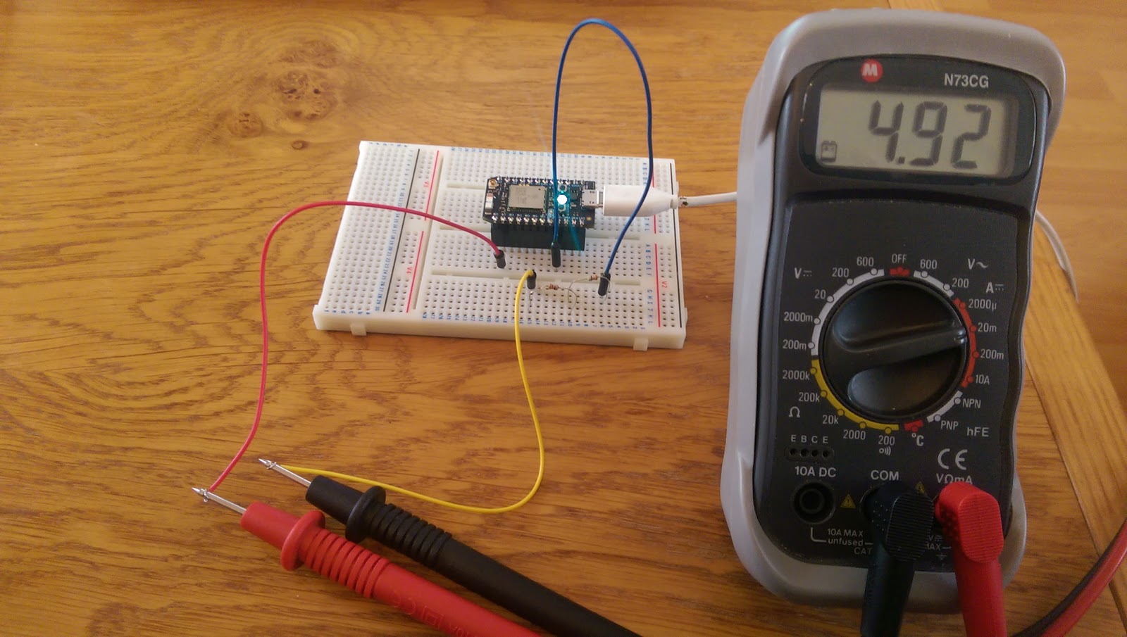
Instead let's jump to measuring the current of a circuit with resistors. When we connect the multimeter in series with a circuit containing different numbers of resistors we can see the current changes. With one 330Ω resistor you get a current of 9.33mA and with two resistors you get 4.93mA.
The current measured in a circuit with one 330Ω resistor is 9.33mA
The current measured in a circuit with two 330Ω resistors is 4.92mA
What these measurements show us is that as the resistance in a circuit increases, the current decreases. This intuitively makes sense as if you put obstacles in the way of something flowing along, the movement will be slowed.
Again we can validate these readings using Ohm's law:
With two resistors:
V = IR
I = V / R
I = 3.3V / (330Ω + 330Ω)
I = 0.005A
I = 5mA
With one resistor:
V = IR
I = V / R
I = 3.3V / 330Ω
I = 0.01A
I = 10mA
Note: Again, the multimeter does not give us completely exact readings so it is expected that they are a little bit off from the calculated current value
Resistance
Resistance is a measurement of how much an object opposes the flow of electrons through it. To measure resistance with your multimeter, connect the probes across the object. The multimeter will then pass a small current through it to measure the resistance. Do not try to measure resistance in a powered circuit as the current will mess with the multimeter's readings.
Here we can verify that the 330Ω resistor does in fact provide that much resistance:
I have been trying to come up with a project for an upcoming session of my company's branch of CoderDojo. This is a voluntary educational group who host classes to teach children about programming and computer hardware. It's pretty tough to come up with a project that a group of children (aged between 6 - 16) can complete in 2 hours and remain interested. Last session we make an augmented reality game using a webcam and the Scratch programming environment. It was really cool and the kids seemed to have fun. However this time we would like to do a project involving hardware too. Another colleague is investigating the Makey Makey and I am trying to come up with something using micro controllers.
An idea I came up with was to get the kids to make booby-traps to either construct an obstacle course or to create a mission impossible style trapped room to protect an artifact. In theory this shouldn't be too tricky as the various sensors are pretty easy to hook up to an arduino/photon and the code to control them is very simple. The obvious trap to start with (to me anyway) is a laser tripwire. This is among the more complicated of the traps to set up, but the outcome will be sweet.
So I spent yesterday putting together a laser tripwire that raised an alarm when tripped to see how it would come together. It took a couple of hours due to me not having made one before, but I'm pretty confident we could get a kid to complete it in under an hour.
I set the circuit up on a breadboard, but you would probably want to solder some of the components together if you wanted to use the tripwire for real. This is just to show you how it all connects.
Photo resistor
We use a photo resistor to detect whether the laser is currently pointing at it or not. The more light that falls on the resistor, the lower the resistance becomes, so we can use this to detect whether the laser is currently pointing at it or not. When set up inside a voltage divider we can translate the variation in resistance to a variation in voltage. We can then measure that voltage to decide whether to sound the alarm or not. We measure V(out) from the voltage divider with the green wire hooked up to analog pin A1. We hook up the input voltage to digital pin D6 which we will pull HIGH at the start of the program to provide a nice steady 3V.
Buzzer
The piezo buzzer is hooked up to 2 digital pins on the photon. We will control the pins from the photon program when we have detected the laser is not pointing at the photo resistor (i.e. someone has broken the beam). A piezo buzzer makes a click sound when you apply a voltage. The faster you generate clicks (by flipping the input between LOW and HIGH) the higher the frequency of the sound produced. I am using the code from the bitsbox component listing to generate the tone.
The Laser
For simplicity I have used a laser module that includes a driver to keep the voltage steady to produce a regulated beam. This makes the component more expensive, but also much easier to use as you just need to hook it up to a 3V power source and voila, frickin' lasers! I obviously have to mention the fact that you shouldn't point this laser into your eyes or the eyes of anyone else. While the laser beam is not strong enough to disintegrate your enemies, it will damage your eyes if you look directly down the beam. So don't. Hook up the laser to pin D6 to power it up and point it at the photo resistor.
Make sure the laser is pointing directly at the photo resistor
Photon Code
The code we need for the tripwire is very simple. We need to read the value from the voltage divider, compare it to a value to decide whether we think the laser has been tripped and then sound the buzzer. Here is the code:
 int sounder_A = D2;
 int sounder_B = D4;
 int tripwire_power = D6;
 int tripwire_input = A1;

 void setup() {

   pinMode(sounder_A, OUTPUT);
   pinMode(sounder_B, OUTPUT);

   pinMode(tripwire_power, OUTPUT);
   pinMode(tripwire_input, INPUT);

   digitalWrite(tripwire_power, HIGH);

   Serial.begin(9600);
 }

 void loop() {

   int tripwire = analogRead(tripwire_input);
   Serial.println(tripwire);

   if(tripwire > 1000) {
     beep(100, 4000);
   }
 }

 void beep(long duration, int freq) {

   duration *= 1000;  //convert the duration to microseconds
   int period = (1.0 / freq) * 1000000; //get the oscillation period in microseconds
   long elapsed_time = 0;
   while (elapsed_time < duration) {
     digitalWrite(sounder_A, HIGH); //Piezo ports go hi/lo then lo/hi
     digitalWrite(sounder_B, LOW); //to generate the tone
     delayMicroseconds(period / 2);
     digitalWrite(sounder_A, LOW);
     digitalWrite(sounder_B, HIGH);
     delayMicroseconds(period / 2);
     elapsed_time += (period);
   }
     digitalWrite(sounder_A, LOW); //kill the output
     digitalWrite(sounder_B, LOW);
 }
Play around with the values to generate whatever sound you want from the buzzer. If you're feeling fancy you can get it to play a tune. Anecdotally I found that the tripwire value read around 150 when the laser was hitting the photo resistor and around 1800 when tripped so I chose a trigger value of 1000 to activate the buzzer.
Break the tripwire and trigger the alarm
You can see the measurements from the serial output here:
My company was organising a hackathon a few weeks back and one of the ideas I wanted to implement was a static electricity detector. This is not as random as it sounds as we have a big problem with static in our office due to the fact we have an artificial grass lawn for a carpet. Despite this looking awesome, it quickly builds up static when you walk across it with rubber soled shoes, leading to small shocks whenever you touch a metal door handle.I want to make a small box that could sit near the main door and beep/light up when it detected the presence of static to warn you of the shock you are about to get it you touch the door handle without discharging first.
This is not my office but it is similar
There are plenty of good articles around the internet on the topic of static electricity, but the best I found was here. This excellent article explains how to make a circuit to detect static electricity and the science behind how it works. I have replicated the circuit incorporating a photon so I can send measurements back to a web server for graphing.
This is the final outcome of the project. The LED turns off in the presence of static and reading are also being sent to a web server over WIFI.
The Circuit
You will need:
2N3819 JFET
A field effect transistor (FET) similar to that mentioned in the article. I chose this one as it was easy and cheap to get hold of from ebay. I bought a bag of 5 for less than £3.
An LED
A breadboard (unless you want to solder the components together
3 wires
A Photon
It should look something like this
Hook the components up like this
Here is the slightly modified circuit from the article. The main differences are the addition of the green wire to feed the readings back to the photon and the ordering of the pins on the FET. I couldn't find anywhere to buy the FET mentioned in the article in the UK so I bought a bunch of similar ones from ebay. Whichever one you use, just make sure the positive wire is connected to the source and the LED is connected to the drain. The datasheet for the FET you use will tell you which order the pins are in.
We will use a digital pin for the power rather than the 3v pin as we want to guarantee a stable voltage to get accurate readings. The power pins fluctuate more than the digital pins pulled high.
The Software
I have uploaded the project containing the photon code and the web server on github here. Compile and flash the contents of src/main/cpp onto the photon and run the scalatra web server as specified in the README instructions.
Generating static
Power up the photon and experiment in holding different items near the FET antenna. I found the most effective test was to run a comb through my hair and hold it close.
The LED is on, no static is detected
One thing I found interesting was that it totally stopped working when I tried to generate static with slightly wet hair (I couldn't be bothered to use a blow drier today). The circuit just wasn't picking up any negative charge at all and I thought maybe I had broken the FET. But then I remembered that someone suggested using humidifiers in the office to combat the static, so googled for how the presence of water affects the generation of static. Long story short, water allows the electrons to move back to where they were originally pulled from (due to the extra conductivity) so the comb was never coming away from my hair with any extra electrons attached, so there was no negative charge.
If I had some balloons handy I would test this by rubbing one against a damp jumper to see if this also shows the same behaviour (presumably it would).
Software is very interesting on it's own, but adding hardware into your projects allows you to investigate simple scientific principals too, which makes computing even more awesome. Yey, science!
When I bought my photon I also bought an Internet Button at the same time. I hadn't come up with a good use for it until recently, when I thought it would make a neat desk notification device for my work Github repositories.
With 4 developers in my team and 10 or so repositories we regularly commit to, I found I was not keeping on top of the pull requests or noticing when people commented on mine. To make this activity more noticeable so I could act on it more quickly I used my Internet Button to flash in different colours according to different triggers.
Push to master triggers a green notification, Pull requests trigger purple notifications
Moving Parts
Github -> AWS API Gateway -> AWS Lambda -> Particle Cloud -> Internet Button
The event triggers come from web hooks you can attach to your repositories in Github. As we've seen in a previous blog post we can export cloud functions to trigger behaviour on your photon. We will use one of these functions as the target of the Github web hook. However we cannot call our function directly as we need to provide the access token to our particle account along with the request payload and the web hooks do not allow you to add custom data so we will need a middle layer. I chose AWS to host this middle layer.
There are many ways to skin this cat but as I have already been playing around in AWS recently I thought I would use this as a learning opportunity to get more familiar with different services available. AWS allows you to quickly set up an API endpoint using the API Gateway and attach it to a back end lambda function written in either Java, Python or NodeJs. Using this setup I created a new endpoint for the web hook to POST to and then a Python lambda to take the request from github and translate it into a payload to send to my particle cloud function.
So unfortunately we have quite a few moving parts to get this working but each part is relatively easy to understand. Let's work backwards from the Internet Button to Github to see how the parts fit together.
The program to flash onto the Button consists of the 3 files main.cpp, InternetButton.h and InternetButton.cpp in the root directory of the project. The InternetButton library originally comes from here but this particular version is my personal fork which has a new function to produce a spinning notification pattern.
The key bit of code to look at here is the exported cloud function:
Here we are taking in a String that will decide what colour notification we want, calling spin 8 times and then turning all the LEDs off again. The notification types accepted here are 'PullRequest' and 'Push', we'll see where they come from in a minute. Take a look in InternetButton.cpp for the implementation of spin. It triggers your chosen colour to light up each LED in turn for a single revolution of the disc. The number you pass into spin is the delay between LEDs so if you want your spin to be faster then enter a smaller delay. Likewise if you want to change the length of the notification, change the number of spins from 8 to whatever you want.
2. Particle Cloud
In order to make our function available in the Particle Cloud all we need to do is ensure our Button is switched on and connected to the internet. When the program starts it exports to function into the cloud with:
Particle.function("notify", notification);
Easy peasy.
3. AWS Lambda
Our cloud function will now run if we make a POST request to the appropriate URL with the correct arguments.
We now need a small program that will make this request for us and inject the arguments. This program needs to be hosted somewhere on the internet to make sure it is always available and running. AWS lambdas are a good way of doing this as it allows you to run a small chunk of code off a trigger without having to worry about any infrastructure.
We will create a lambda with the contents of call_particle.py. I used this tutorial to help, which also covers the API Gateway we will see in the next section.
The python handler receives an event object containing the metadata sent from Github. From this object we can work out whether the event was a push or a pull request. If it was a push we only continue processing if it was a push to master as we are not interested in other branches. Once we know what our notification type should be we create a new POST request and send our particle access token along with our function argument off to the Particle Cloud API.
If you are not committing your code somewhere public you can just include your particle access token and device ID directly in the python code instead of reading them out of the event. However as I wanted to make this code public I have taken steps to inject my data in the next step.
4. AWS API Gateway
Now we have our lambda that will call our particle function, we just need a way of exposing it on the internet so it can be accessed by Github. We are going to do this using the API Gateway. Continue following the tutorial from the previous step to create a new resource with a POST method.
This is what my setup looked like:
I added some extra config in the Integration Request section to inject my particle access token and device ID into the request before it hits the lambda. If you want to do the same, add a new mapping template of type 'application/json' with the following content:
This will perform a transformation of the request before it is passed to the lambda via the event object. The original payload will be nested inside the 'body' value and 2 new keys will be added for the particle credentials. If you do not want to perform this mapping step you will need to modify the python script to remove the 'body' nesting as the original request will now be at the root of the event object.
Follow through the tutorial until you have deployed your endpoint to a stage to give you an invoke URL. We're almost done!
5. Github web hook
We will now attach a web hook to our repository to make a POST request to our new endpoint when someone pushes or makes a pull request.
Go to your repository and open the Settings
Click on 'Webhooks & Services'
Click 'Add webhook'
Enter your invoke URL from the API Gateway along with the full path to your resource.
Underneath your webhook configuration is a section called 'Recent Deliveries'. This will show you the last few requests that were sent to your endpoint. This is really useful for seeing the exact structure of the payload so you know how to pick out the relevant data in your lambda. You can also resend particular payloads for faster turnaround time when testing.
We're done!
Plug in your Internet Button and push some code to the master branch of your repository. The Button should do a green spin. Commit to a branch and create a pull request for a purple spin. Any comments on the pull request will also trigger a purple spin. Conversation comments are a separate event to comments on the diff which is why we included 'Issue Comment' in our trigger configuration.
Have a play and add more notification types by attaching more triggers, updating the event_type mapping in the lambda and choosing a colour mapping in the particle code.
Before building the circuit I thought it would be best to write the program to source the tweets and send them to the photon first. This way we can see exactly how much data to expect and what form it will take.
I wrote a little java program to do this. You can download it from github here along with the cpp photon program. The program searches twitter for Christmasy tweets within the London M25 (that's where I live, so obviously you can change this to an area that interests you). It polls every minute for tweets in 5 different locations, north, south, east, west and central London.
The twitter search string is:
""christmas OR xmas OR "joyeux noel" OR weihnachten OR navidad OR "boze narodzenie"
Hopefully this will cover the majority of Christmas related tweets, including English, French, German, Spanish and Polish languages. Amusingly I originally only searched for 'noel' rather than 'joyeux noel' but there appeared to be a Noel Gallagher concert on recently so I got a lot of false positives. Goes to show you should inspect your results!
The photon needs to be running for the java program to run successfully as you get a HTTP 400 Bad Request from the particle server when your cloud function isn't available. But once the photon is running and the java program begins, you will see the tweet locations being logged to the serial monitor.
Now we have data, we can start making a circuit to visualise who is the most Christmasy.
Given that we have 5 possible sources of tweets, I imagine having 5 sets of LEDs each flashing at a rate/pattern that indicates the total count/frequency of tweets being received.
In the run up to Christmas I fancy making something Christmassy!
My first thought was visualising Christmas related tweets through IFTTT. After linking my photon to IFTTT and playing around with a few recipes it was clear that the triggers were just not reliable enough and the correct tweets were not coming through.
So let's create something from scratch.
First we need a mechanism for a notification to be sent to the photon to trigger the visualisation. This is done by exporting a function to the particle cloud that will give us a REST API endpoint to poke.
This program will export a function called 'tweet' which takes in a String (max length 63 characters) and pull the D7 pin high when it is called. This is the pin with the blue LED next to it on the board so we can easily see it is working without constructing a circuit. The function also writes a log line to the serial output so we can see what the message is.
   $ particle compile p
   $ sudo particle flash --usb photon_firmware_xxx.bin
   $ sudo particle serial monitor
Now we are connected to the photon and listening for log messages.
When you export a cloud function a REST endpoint is created in the format: